

1: About microwave
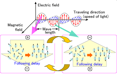
Since the electromagnetic wave is propagated by the interaction of electric field and magnetic field, it can also be propagated in a vacuum.
Electromagnetic wave is a wave that has two elements, such as wavelength and frequency. Wavelength is about the length of top to top of the wave, frequency is number of waves that appears in a second.
The velocity of electromagnetic wave in a free space, such as vacuum and air, is constantly 300,000km per second regardless of frequency. Wave length equals to this divided by frequency.
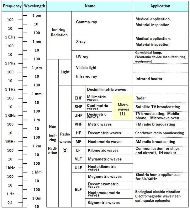
As shown in Table 1, electromagnetic wave is called differently depends on frequency. It is used in various applications according to their characteristics. Light is also a kind of electromagnetic wave. The electromagnetic waves that are less than 3000GHz, is classified as radio wave. Radio wave that has frequency of 300MHz to 300GHz (wave length of 1m to 1mm) is known as microwave.
Microwave has been applied to communication, radio telescope for astronomy, radar surveillance system, and also to GPS positioning system known as car navigation system. Heating is another application of microwave.
Reference
[1] IEC 61307 Edition 3.0 2011-05 Industrial microwave heating installations
[2] ITU recommendation ITU-R V.431-8 (08/2015)
2: About the frequencies that can be used for Microwave heating device
ITU (International Telecommunication Union) allocates the available frequencies of radio wave that depends on purpose of use.
And, the international standard CISPR11 indicates the frequency bands used by industrial, scientific and medical equipment (ISM equipment) as the ISM fundamental frequencies, limits of radio wave disturbance and methods of measurement.
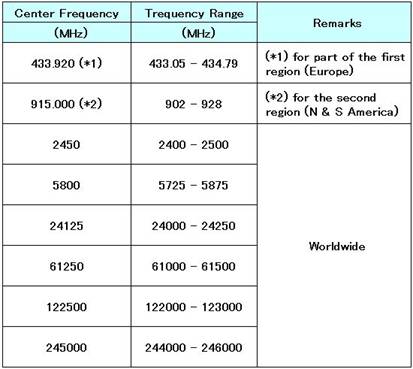
The ISM fundamental frequencies of microwave from 300MHz to 300GHz (wave length of 1m to 1mm) by the ITU in the CISPR11 are shown in Table 2. 433.92MHz has been recognized as ISM frequency in some countries, in the first region (Europe). 915MHz has been recognized as ISM frequency in the second region (North and South America). ISM frequencies that can be used worldwide is the ISM frequency of 2450MHz or higher.
However, they are finally decided by the laws of each country.
In Japan, the Radio Law has been in place to prevent telecommunication interference, and regulates at very strict limits. Besides, in 2015, the J standard: J55011 (H27) was established by modifying CISPR11 according to the actual situation in Japan. And, the Radio Law was amended at the same limit values of the J55011 (H27).
Since the Radio Law doesn’t regulate the limit values to the ISM frequency bands, most of all manufacturers select the ISM frequency for their equipment. Because, in such cases, they only have to consider the safety regulations of which limits are much larger than the Radio Law. In contrast, the equipment that use radio frequencies other than the ISM frequency need a large-scale countermeasurement for radio leakage to meet the limits of Radio Law, such as, radio wave shields for equipment installation room, or for entire building.
This is why various industrial heating equipment is using ISM frequency, including the microwave oven for household.
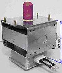
The 2450MHz is the most popular among ISM frequency bands due to not only being usable in any countries in the world, but also existence of a microwave oscillator tube shown in Figure 1. The relatively inexpensive magnetron (Output: 300W to 10kW) that is compact built, light weight, and permanent magnet attached, is also a huge contribution to market expansion of the 2450MHz band.
3: The principle of microwave heating
You may have the experience of not being able to watch BS TV broadcasts when it is raining hard. According to reference [3], the frequencies at which water absorbs microwave most efficiently are around 10 GHz at 0 deg. in C and around 18 GHz at 20 deg. in C.
The frequency of microwave oven is 2.45GHz (2450MHz). And the frequency of BS broadcasting TV is around 12GHz. You can probably understand the reason for not being able to see the BS broadcasting TV in hard rain by now. It is that BS airwaves have been absorbed by the rain. Power of BS airwaves is weak, so rain will not be heated. But in principle, rainwater is heated by the absorbing power from BS airwaves.
In this chapter we explain not only about, “The principle of microwave heating”, “Microwave power absorbed by the dielectric”, “The depth of microwave penetration into the dielectric”, and “Dielectric properties of the dielectric”, but also “Microwave power absorbed by the metallic plate”.
(1) The principle of microwave heating
IEC (International Electrotechnical Commission) defines, Microwave heating is to heat dielectric materials through mainly their molecular motion and their ionic conduction by the action of electromagnetic waves of 300MHz to 300GHz [4].
The principle of the microwave heating is very difficult. And it’s not easy to explain, but the following will give you a rough idea.
“For the vibration of microwave electric field, for example, when permanent electric dipole in the dielectric materials follows the oscillation of the microwave field slightly later, i.e., to the change of microwave field, in case permanent electric dipole changes with phase lag, this phase delay is the resistance to change of microwave field. Then, the permanent electric dipole will be heated by this resistance.” Briefly, “The permanent electric dipole is forced to vibrate while resisting, and generates heat by this action.”
Followings are explanation with figures:
The principle of microwave heating described in using Figure
Figure 2 shows the structure of water molecules that are discussed as representatives of the permanent dipole. Water consists of two hydrogen atoms and one oxygen atom. It doesn’t have electric charge as a whole, an oxygen atom is bounding with two hydrogen atoms at an angle of 104.5°. Those atoms take a little charge of each minus(-) and plus(+) to form a dipole.
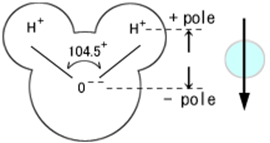
Then as shown in Figure 3, when there is no external electric field, it has set a balance. But when placed in external electric field, dipole will turn towards the electric field.
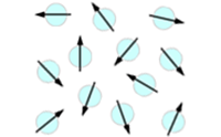
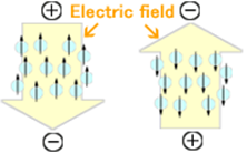
Figure 3 Direction of dipoles influenced by external electric field
For example, when the water is irradiated with radio wave, it means to give an electric field for alternating. In case of microwave oven, vibration of 2450 million times plus and minus is replaced per second.
Figure 4 shows a case where a too much lower frequency of radio wave is irradiated to the permanent dipole of water. In this case, the permanent dipole will immediately follow the directions of electric field. So in this case, water doesn’t generate heat.
On the other hand, Figure 5 shows a case where a too much higher frequency of radio wave is irradiated to the permanent dipole. In this case, since electric field changes its direction too fast, dipole won’t be able to follow. Then, water does not generate heat in this case also.
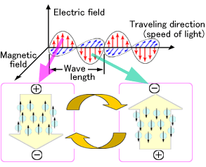
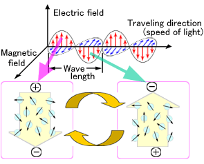
In contrast to these, Figure 6 shows a case where moderate frequency of radio wave is irradiated to the permanent dipole. In this case, the permanent dipole changes a little behind the electric field. During the time delay, water is absorbing energy from radio wave and generates heat. And, this moderate frequency is the microwave.
(2) Microwave heating formula and the dielectric properties of materials
(A) Absorbed microwave power by the dielectric materials (theoretical formula) [5]Equation 1 shows microwave power P1 absorbed by the dielectric in a theoretical formula. Relative permittivity of the dielectric material εr and dielectric loss angle of the dielectric material tanδ show the characteristics of dielectric material. In Equation 1, multiplication of relative permittivity εr and dielectric loss angle tanδ is known as the dielectric loss factor (also referred to as loss factor). This factor shows the level of microwave power absorption by the material.
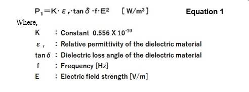
On the other hand, E in Equation 1 is the electric field strength which will be determined at the design of applicator in the equipment as well as at conditions of the dielectric in the applicator. So, there is no way to find out the actual electric field distribution in the dielectric without using microwave field simulator by PC. However, if the dielectric is liquid, its absorbed microwave power can be calculated as described in (B).
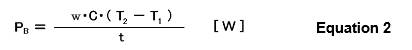
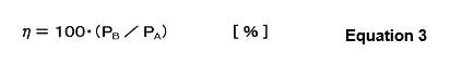
In the applicator, a vessel with liquid w [g] (at initial temperature T1 [deg. in C]) is irradiated at microwave power PA [W] for t [s]. Then, the liquid becomes T2 [deg. in C]. And, the specific heat of the liquid is C [ J /(kg・K)]. Then, microwave power PB [W] absorbed by the liquid is given by Equation 2. And, the heating efficiency η is given by Equation 3.
The microwave penetration depth D from the surface of the dielectric to inside is defined as depth that is 50% of the surface power. And, the formula for the penetration depth is given by Equation 4.

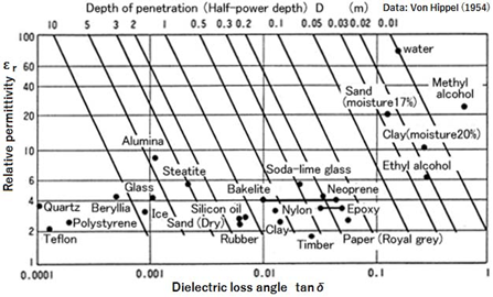
We have explained that relative permittivity of the dielectric material εr and dielectric loss angle of the dielectric material tanδ show characteristics of material (dielectric) at section (A).
Figure 7 is a characteristic diagram showing the relative permittivity εr and the dielectric loss angle tanδ of various materials. As a result, roughly materials on up-right which has a large absorption of microwave’s penetration depth is shallow, and materials on below-left which has a little absorption of microwave’s penetration depth is deep. Of course, correctly, the magnitude of absorbed power by the dielectric has to be compered by the dielectric loss factor (εr・tanδ).
(3) Microwave heating to metallic plate
According to definition of microwave heating by reference [4], you might think that microwave can only heat dielectric materials. However, metal can also be heated by hysteresis loss or Joule loss of microwave.
In the case of metallic or metallic oxide particles, for example of iron, the microwave penetrates the inside while heating on the surface of particles. However, in the case of metallic plate, the microwave can penetrate only a little, and most of it is reflected. So, the absorbed microwave power is not so much.
In this chapter, the absorbed microwave power on the surface of the metallic plate will be discussed:
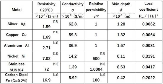
(A) Skin depth of microwave penetration in the metallic plate [8]Equation 5 shows the skin depth δ of microwave penetration to the metallic plate,
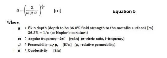
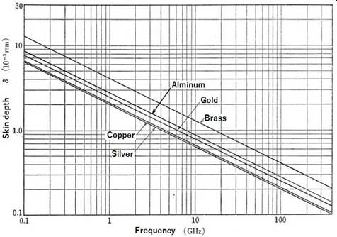
Figure 8 shows frequency characteristics on the skin depth δ of non-magnetic metals [9]. For example, the skin depth of Aluminum at 2450MHz is approx. 1.67μm. Therefore, 20μm of Aluminum plate (approx. 12 times of its skin depth) is equivalent to approx. 104dB of attenuation. So, if you irradiate 1000kW at the surface of the aluminum plate, you will see only 0.1mW at the other side of the plate.
Then, you can easily understand that 2.45GHz of microwave cannot pass through 0.5mm thickness of aluminum plate.
Since waveguide thickness of Micro Denshi is 2.5mm, you would not need to worry about microwave leakage through the waveguide wall.
Equation 6 shows the absorbed microwave power by the metallic plate. And, this is the same as the loss (Joule loss) when a current corresponding to the magnetic field strength on the thin film surface flows through a metallic thin film of thickness δ.
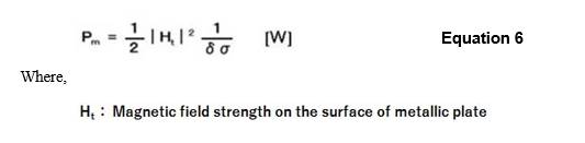
Therefore, Pm/|Ht|2, that is, 1/ (2δσ) represents a difference in loss depending on the type of metals and may be called as a loss coefficient.
(C) Calculated results on the absorbed microwave power of various metallic platesTable 3 shows skin depth and loss coefficient of various metallic plates at 2.45GHz microwave. The skin depth of magnetic metals such as nickel and carbon steel are shallower than that of non-magnetic metals such as silver, copper, aluminum and so on.
Reference
[3] Chaplin, M. F., Water Structure and Science, Applied Science London South Bank University, http://www1.lsbu.ac.uk/water/microwave_water.html, browse on September 18, 2019
[4] IEC 60050-841:2004 International Vocabulary (IEV)-Part 841: Industrial electroheat
[5] Handbook on Food Using Microwaves & Microwave Ovens, Atsuko Higo, Nippon Kogyo Shimbun, 1987, p13
[6] Handbook on Food Using Microwaves & Microwave Ovens, Atsuko Higo, Nippon Kogyo Shimbun, 1987, p16
[7] Handbook on Food Using Microwaves & Microwave Ovens, Atsuko Higo, Nippon Kogyo Shimbun, 1987, p16
[8] Fundamentals of Microwave Engineering, Toshio Akimoto, Yukihito Matsuo, Hirokawa Shoten, 1968(4th), p42
[9] Microwave Circuit of Electronic Circuit Design series, Munenori Ishii et al, Nikkan kogyo Shimbun, 1969, p23
[10] Fundamentals of Microwave Engineering, Toshio Akimoto, Yukihito Matsuo, Hirokawa Shoten, 1968(4th), p43
[11] Science Chronology 2009 (desk version), National Astronomical Observatory, Maruzen, 2008, p408
[12] http://hyperphysics.phy-astr.gsu.edu/hbase/Tables/magprop.html#c2, browse on September 5, 2019
[13] http://www.jssa.gr.jp/contents/faq-article/q6/, browse on September 5, 2019
[14] https://www.toishi.info/metal/teikou.html, browse on September 5, 2019
4: The characteristics of microwave heating
Microwave heating has excellent features not found in other heating methods (conventional heating method).
They are as follows:
・Internal heating
・Rapid heating, Select heating
・High heating efficiency, Rapid response and temperature control
・Heating uniformity, Clean energy
・Good working and operating environment
Will describe each categories below:
(1) The internal heating
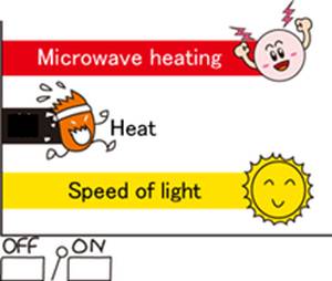
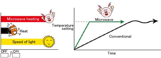
As shown in Figure 9, microwave will reach the object to be heated at the same speed of light. Then it enters into the object as a wave, and by getting absorbed, the object generates heat. Therefore, as shown in Figure 10, microwave heating is internal heating.

(2) Rapid heating
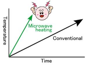
As shown in Figure 10, in conventional heating, the object’s temperature rises by spreading heat energy from the surface to inside (external heating). On the other hand, by microwave heating, the object will generate heat on their own by the penetration of the microwave. Not necessary to consider about the heat conduction. That is why rapid heating is possible by microwave.
Even if the object is deeper than the depth of the microwave penetration, it will be heated by microwave till the depth of microwave penetration from the surface of the object, and then, the center of the object will be heated by the conducted heat energy from the heated portion of microwave. So, the heating time to the center of the object is shorter than the case of external heating.
As shown in Figure11, compared to the conventional heating which is heated from the surface, the microwave heating is faster.
(3) Selected heating
Microwave heating, as shown in Figure 7, there is a difference in microwave power absorption depending on the material.
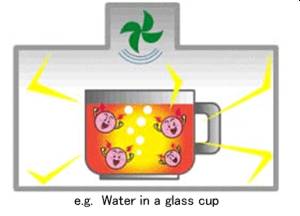
For example in Figure 7, a borosilicate glass is sold as microwavable glass container. When this glass is heated with water in it, only water gets heated. That’s because microwave power absorption of the glass is ignored since there is only 1/3000 of water.
Therefore, as shown in Figure 12, when a good material of container is selected, microwave can only heat the object and heat efficiency improves substantially.
(4) High heating efficiency
Microwave penetrates into the object at the speed of light. And the object to be heated generates heat on their own. You get high heating efficiency because no need to consider the heating losses of air inside the heating furnace.
(5) Rapid response and temperature control
Microwave penetrates into the object at the speed of light. And the object to be heated generates heat on their own. So it allows rapid response. For example, you can start and stop the heating instantly. In addition, by the adjustment of microwave output, you can control the amount of heat energy generated inside the heated object. Therefore as shown in Figure 13, you can instantly respond to the temperature changes of the object to keep the temperature setting.
(6) Heating uniformity
Each part of the heated object generates heat, so even for those objects with complicated shape, it can be heated relatively uniform. To keep the heating uniformity, stirrer, turntable, and belt conveyor is used for uneven heating related to wave length.
(7) Clean energy
Microwave doesn’t require a medium, because it propagates only by interaction of electric fields and magnetic fields. It can propagate in a vacuum. It reaches the object and penetrates without heating the air. The heated object generates heat by absorbing microwave energy to convert it to heat energy. Therefore, it can be said as clean energy because it doesn’t heat the air during process.
(8) Good operation and work environment
Conventional heating requires a heat source, and the temperature rises not only of heated object, but also of heat source and the heating furnace. So the temperature of room equipped heating furnace goes high because of radiant heat. This is an operation and work environment issue. On the other hand, microwave heating only uses electricity to generate heat of the object. The temperature of the object only rises, not the furnace. And there is little radiant heat, so it’s possible to keep operational and good working environment.
5: The basic structure of microwave power application apparatus and microwave devices
Electronic devices that generates microwave are magnetron, klystron, gyrotron, etc. Magnetron is comparatively inexpensive and it can generate a relatively large power the microwave. Magnetron is a type of electronic vacuum tube that has been also used in the microwave oven for household. We, MICRODENSHI, primarily use the 2450MHz band magnetron. We manufacture microwave power application apparatus that has 300W to 300kW outputs.
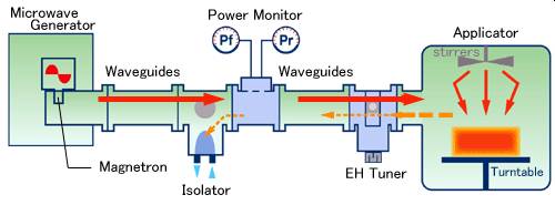
(1) The basic structure of microwave power application apparatus
In Figure14, shows the basic structure of microwave power application apparatus. Microwave that is generated by magnetron built inside the microwave generator, waveguide, isolator, power monitor, EH-tuner, then reaches the applicator to heat the object to be heated inside the applicator.
In here, microwave that is generated by the magnetron is called the traveling wave (or incident wave). On the other hand, microwave that is reflected by the applicator is called the reflected wave (or reflection wave).
The transmitted wave power is obtained by subtracting the reflected wave power from the traveling wave power.
In the basic structure shown in Figure14, when the EH tuner is adjusted while observing the value of the reflected wave power displayed by the power monitor to make the reflected wave power zero, the traveling wave power is all, that is the microwave power consumed after the EH tuner.
The reflected wave power fluctuates greatly due to the rotation of the stirrer and/or the turntable in the applicator. In this case, the EH tuner shall be adjusted so that the average value of the reflected wave power becomes the minimum.
Then, the heating efficiency becomes the maximum.
(2) The functions of each microwave device
(A) Microwave generator: A device that generates microwave.
A magnetron is mounted on the launcher waveguide, and the microwave generated by the magnetron is radiated to the launcher waveguide. The power supply that operates the magnetron is also part of the generator.
The end of the launcher waveguide is open, and a standard waveguide can be connected. The standard waveguide to be connected is WRJ-2/WRI-22 with the standard flange of BRJ-2/FUDR-22. Therefore, be sure to connect the microwave devices up to the applicator as shown in Figur14 for the operation test of the generator. Because, it is dangerous to test the generator alone.
(B) Isolator:A device, sends traveling wave directly to the applicator, and absorbs reflected wave by built-in dummy load to avoid returning back to the generator. Therefore, the magnetron in the generator can be operated at matched load.
The reflected wave which occurs by rotation of the turntable and/or the stirrer in the applicator is also absorbed by the isolator. Besides, it can also absorb the microwave from other generators if the applicator have multiple generators. So, the isolator is very important device for the high power magnetron to continue stable operation.
(C) Power Monitor: A device that monitors traveling wave power and reflected wave power in the rectangular waveguide. Must be careful when you can read a reflected wave power as well as a traveling wave power. Because, indicated values of both powers may contain a lot of error.
Power monitor by Micro Denshi show the power accurately, even when magnetron is driven by different power supply.
(D) EH-Tuner: There are two kinds of tuners, which are three stub and EH. EH-Tuner is recommended for easy adjustment. By adjusting E- or H-tuner, the magnitude of microwave reflection changes to minimum at the tuner section. And, by adjusting H- or E- tuner, the reflected power becomes zero.
This means that, by adjusting both E- tuner and H- tuner, the EH- tuner generates a same magnitude reverse phase wave to counter the reflected wave. And as a result, the reflected wave has been denied.
When the reflected power wave value is zero on the display of the power monitor, power consumption of after the tuner including the applicator is maximized. This condition is called “The matching”
(E) Applicator: A heating tank that heats the object placed inside by irradiation of microwave. Depending on the application, there are a variety of shapes, such as batch type, conveyor type, waveguide type, etc.
Micro Denshi’s applicator has been devised to minimize the reflection caused at the junction of waveguide.
(F) Waveguide: Microwave propagates in the interaction of electric and magnetic fields. Microwave is transmittable when the cross section of metallic pipe is larger. In Japan, for the microwave heating equipment, 2GHz standard rectangular waveguide of which rectangular cross section is 109.2mm by 54.6mm is used. (Standard waveguide: WRJ-2/WRI-22, Flange: BRJ-2/FUDR22)
The standard waveguide supplied by Micro Denshi has a 2.5mm aluminum wall which the 2.45 GHz microwave cannot pass through as explained in 3. (3) (A).
This concludes the “Basic knowledge of microwave heating”.
For specific applications of microwave heating, please refer to other items on this website.


Copyright 2020 Micro Denshi Co., Ltd.
All Rights Reserved.